Electrical systems in the maritime industry have evolved from auxiliary installations into a core part of vessel engineering. This shift responds to three growing demands: efficiency, safety and operational availability. In an isolated environment—without a stable external grid during navigation—the onboard electrical system must ensure continuity of service, manage variable loads and maintain reliable protections under vibration, humidity, salt spray and demanding operating conditions.
In this article we provide a practical overview of the fundamentals of marine electrical engineering: how power is generated and distributed onboard, what load balance means for correct sizing, which systems are considered essential or emergency, and which maintenance practices help reduce failures and time out of service.
Onboard electrical architecture: generation, distribution and protection
On a vessel, electricity is organised as an integrated system covering generation, distribution and, in some cases, energy storage. Unlike shore installations, where an external grid provides stability, ships operate their own microgrid, with redundancy and prioritisation logic: in the event of a fault, the vessel must keep essential services available, maintain safe manoeuvring capability and preserve response capacity.
In general terms, a marine electrical system includes the following elements:
- Generation: main generator sets (typically diesel-driven), and in some cases auxiliary generators depending on the operating profile.
- Storage: batteries for specific services, peak shaving or backup, especially in hybrid configurations.
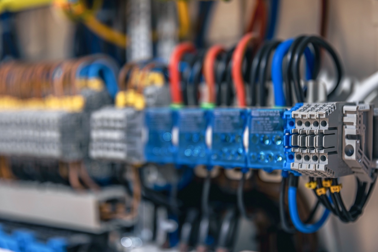
- Distribution: main switchboard, emergency switchboard and distribution networks by zones/circuits.
- Conversion: transformers and converters to adapt voltages and supply equipment with different requirements.
- Infrastructure: cabling and routing with marine-grade protection and segregation criteria.
- Protection and monitoring: relays, RCDs, protection coordination, monitoring and alarms.
On modern vessels, redundancy is not an “extra”—it is part of the design. Segregated switchboards, separated essential services and the ability to feed critical loads from the emergency system ensure that a single fault does not translate into a total loss of operational capability.
Energy sources and the shift toward electrification
The most widespread solution remains electrical power generated from internal combustion engines—mainly diesel—supplying ship services and, in some cases, propulsion (diesel-electric). However, the industry is moving toward more efficient and sustainable configurations, driven by operating costs, environmental requirements and operator expectations.
Depending on the vessel type and mission, common configurations include:
- Diesel-electric: diesel engines drive generators and electric power feeds propulsion and services, offering strong operational flexibility.
- LNG: a cleaner alternative to diesel for certain operating profiles.
- Hybrid: combining engines and batteries to optimise consumption and respond efficiently to demand.
- Renewables integration: solar/wind support in specific applications, typically as a complement rather than a primary source.
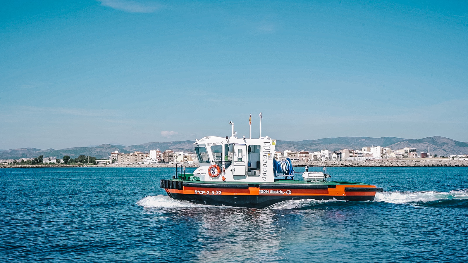
- Fully electric: feasible for defined operating profiles where the design is optimised around autonomy and charging.
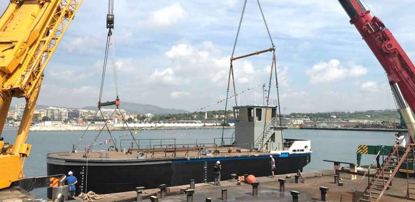
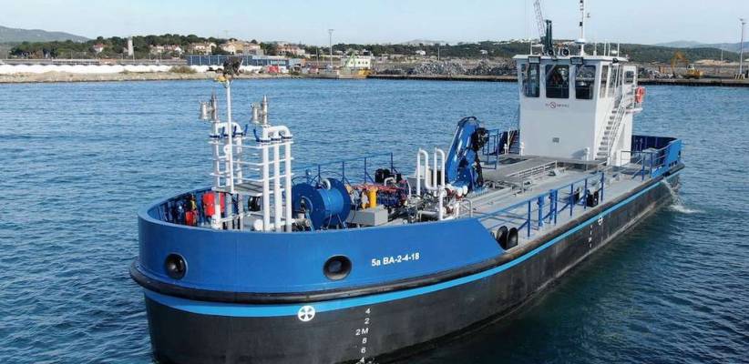
An example of this evolution is the Castalia electric vessel, conceived as a zero-emissions platform for specific operational scenarios. Projects like this require the electrical architecture to be designed as a complete system: storage, distribution, protections, energy management and safe operation under real conditions.
Load balance: the foundation of correct electrical sizing
Load balance is one of the fundamental calculations in marine electrical design because it defines the real power requirement onboard under operational criteria. It is not simply a sum of nameplate ratings; it is an understanding of which consumers operate simultaneously, under which scenarios and with what utilisation factors. A well-built load balance avoids two common risks: costly oversizing (weight, complexity and CAPEX) or insufficient power (service loss, operational risk and real limitations onboard).
In practice, load balance includes: identifying consumers, classifying them by criticality (essential, important, normal), defining rated power, applying demand factors, and calculating totals across scenarios (navigation, manoeuvring, port, emergency). Expected demand is obtained by applying simultaneity and partial-load factors, enabling the correct sizing of generator capacity and distribution with adequate operational margin.
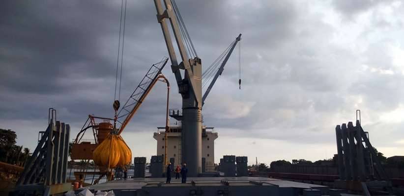
On barges and commercial units, onboard generation is typically delivered through generator sets (prime mover + alternator + regulation + protections). On larger vessels, multiple generators are often run in parallel to share load and ensure redundancy, supported by synchronisation and load-sharing logic.
Lighting, safety and consumption: what drives day-to-day operation
Lighting is a useful example of how an apparently “secondary” system becomes operationally critical. On professional vessels, lighting does not only support habitability—it directly impacts safety, operation and evacuation. That is why ships distinguish between general lighting, task lighting, statutory navigation lights, emergency lighting and low-level escape route systems, among others.
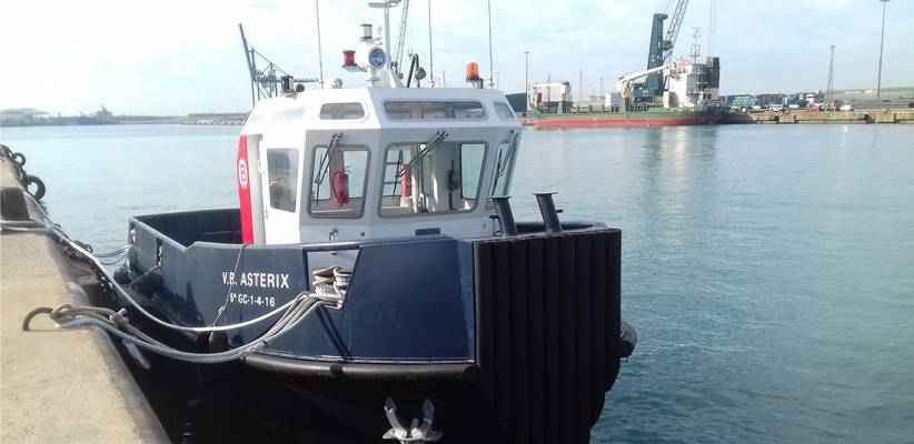
Modern vessels also feature electrical outlets and circuits designed for industrial use and maintenance, adapted to the marine environment (ingress protection, sensitive RCDs, voltage selection according to global operation and measures to reduce galvanic corrosion). When the vessel is alongside, external supply (“shore power”) can reduce fuel consumption and noise, provided the integration is correctly engineered and protected.
In parallel, the bridge concentrates navigation and communications equipment that requires stable power and redundancy: radar, integrated navigation systems, communications and technical alarms. These loads must be considered from the design stage, because they cannot tolerate degradation—continuity directly affects safety and operational capability.
Electrical maintenance: reliability and prevention
Marine electrical maintenance is not only corrective. Under vibration, humidity and variable loads, prevention is what separates continuity of service from recurring failures. Maintenance plans are typically aligned with class requirements, internal procedures and manufacturer recommendations, focusing on inspection, testing and verification of protections.
Typical tasks within an electrical maintenance plan include:
- Periodic inspection of connections, torque points and cable condition.
- Insulation and resistance testing on critical circuits.
- Verification and coordination of protections (relays, RCDs, selectivity).
- Generator/alternator maintenance and regulator checks.
- Verification of batteries, chargers and emergency systems.
- Calibration of instrumentation and review of control systems.
When scope includes modifications, modernisation or integration of new consumers—such as automation upgrades, distribution changes, new protection logic or adaptation to new operational requirements—the most efficient approach is to treat it as an integrated project. At SYM, this work is delivered within ship repair services and, where relevant, as part of ship conversion projects, where technical planning reduces rework and minimises time out of service.
The trend is clear: more electrification, more automation and deeper energy integration. In the naval sector, the goal is not “more technology,” but translating it into safety, efficiency and real availability onboard.